In the last three posts I went through the basic steps to send data from an Android device to an Arduino using a bluetooth serial module. That was fun and all but it would be better if the Arduino could send data back to the Android device. With functionality like that there a lot more plausible uses for the technology. For this example I am going to go through the steps to make a 4 channel voltage logger but with a few minor changes this could be used to send/receive practically anything.
All files used are available on GitHub here.
Like last time, lets get the Arduino stuff out of the way first. For this project I have made a simple sketch and circuit that takes four analog inputs A0-A3 and then converts the values to 2dp float voltage values. The values are then displayed on the LCD screen and transmitted on the serial port (in our case, it is going to a Bluetooth module but for testing the serial port utility on the Arduino IDE will do for now). This process happens every 2000ms so that it is easy to follow what is happening. And just so we know that comms are being established both ways I have put in the ability to change the state of the built in LED on pin 13 on/off. Pretty standard wiring but here is a diagram incase you are unsure. I actually used a 4×20 LCD screen but the pin outs are usually the same or very similar and code is very easy to change for 2×16 etc. Also decided to use an Arduino Nano for this – love it!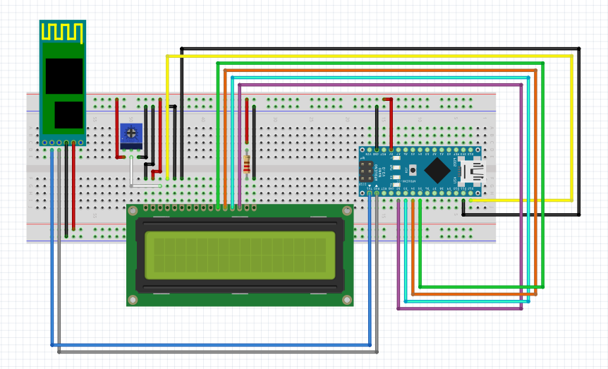 Below is the sketch for the Arduino. It serves three simple functions:
1. Reads in sensor values from A0-A3 and converts them to float values in the range 0-5. So if 5V is put on A0, the sensor will be at 1023 which is converted with a mathematical function to 5.00.
2. Prints the converted values of the sensors on to an LCD screen. I used a 4×20 but if you use a smaller screen you should only need to change a few lines of code.
3. Sends converted sensor values over serial to another device, in this instance the bluetooth module. Using a set of print statements and a for loop the data string will look something like this #1.23+2.34+3.23+2.43+~ The ‘#’ and ‘~’ are used by the Android app to determine the validity and length of the incoming string, as it knows ~ is the end. From here it can find the values of the four sensors using string methods. I used ‘+’ to separate the values for my own benefit, as it makes things clearer to see on hyperterminal etc, they aren’t needed for any other reason.
#include <LiquidCrystal.h>

int led = 13;
LiquidCrystal lcd(12, 11, 5, 4, 3, 2);
// Pins used for inputs and outputs********************************************************
const int analogInPin0 = A0;// Analog input pins
const int analogInPin1 = A1;
const int analogInPin2 = A2;
const int analogInPin3 = A3;

//Arrays for the 4 inputs**********************************************
float sensorValue[4] = {0,0,0,0};
float voltageValue[4] = {0,0,0,0};

//Char used for reading in Serial characters
char inbyte = 0;
//*******************************************************************************************

void setup() {
  // initialise serial communications at 9600 bps:
  Serial.begin(9600);
  lcd.begin(20, 4); //change to 16, 2 for smaller 16x2 screens
  pinMode(led, OUTPUT);
  digitalWrite(led, HIGH);
}

void loop() {
  readSensors();
  getVoltageValue();
  printLCD();
  sendAndroidValues();
  //when serial values have been received this will be true
  if (Serial.available() > 0)
  {
    inbyte = Serial.read();
    if (inbyte == '0')
    {
      //LED off
      digitalWrite(led, LOW);
    }
    if (inbyte == '1')
    {
      //LED on
      digitalWrite(led, HIGH);
    }
  }
  //delay by 2s. Meaning we will be sent values every 2s approx
  //also means that it can take up to 2 seconds to change LED state
  delay(2000);
}

void readSensors()
{
  // read the analog in value to the sensor array
  sensorValue[0] = analogRead(analogInPin0);
  sensorValue[1] = analogRead(analogInPin1);
  sensorValue[2] = analogRead(analogInPin2);
  sensorValue[3] = analogRead(analogInPin3);
}
//sends the values from the sensor over serial to BT module
void sendAndroidValues()
 {
  //puts # before the values so our app knows what to do with the data
  Serial.print('#');
  //for loop cycles through 4 sensors and sends values via serial
  for(int k=0; k<4; k++)
  {
    Serial.print(voltageValue[k]);
    Serial.print('+');
    //technically not needed but I prefer to break up data values
    //so they are easier to see when debugging
  }
 Serial.print('~'); //used as an end of transmission character - used in app for string length
 Serial.println();
 delay(10);        //added a delay to eliminate missed transmissions
}

void printLCD()
{
  for (int i = 0; i<4; i++) //change 4 to 2 if using small screen
  {
    lcd.setCursor(0, i);
    lcd.write("Sensor");
    lcd.setCursor(7, i);
    lcd.print(i);
    lcd.setCursor(8, i);
    lcd.print(" = ");
    lcd.setCursor(11, i);
    lcd.print(voltageValue[i]);
    lcd.setCursor(15, i);
    lcd.print("V");
  }

}
void getVoltageValue()
{
  for (int x = 0; x < 4; x++)
  {
    voltageValue[x] = ((sensorValue[x]/1023)*5);
  }
}
Load that sketch on to your Arduino and power it all up. The voltage values should display on the screen if all ok. Put a lead from any of the pins A0-3 to 5V to check the sensors work correctly and the screen updates the results. Momentarily disconnect the bluetooth module Tx and Rx from the Arduino and open the serial monitor in the Arduino IDE. You should see the voltage values being transmitted every 2 seconds in the form #1.23+1.54………~. Just send a 1 and a 0 back to the Arduino from the monitor to check the LED on pin 13 turns on/off and that is the Arduino side done and proved working. Mine looked like this:
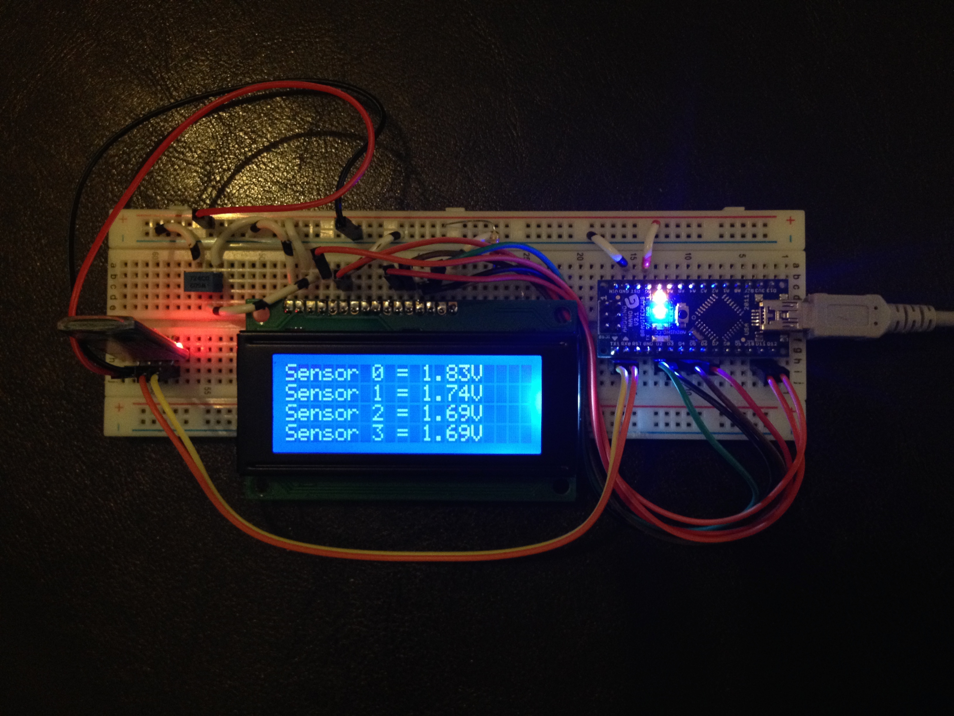
Not the neatest of things but it worked for me! On to the Android part in part 2.
Hey, i’m inspired with your work. i’m making a similar app but the subject is a bit different. i have the same circiut but there is no lcd and i dont need one. the purpose of my app is to get data from arduino in degrees as the sensor is moved in various angles and to print a simple graph of that angles which were recorded by the movement..i would be glad if u could please help.
Sounds fun. All you have to do really is work out what format you will send the data to the android app, how often and then create a graph. There are a lot of graph APIs available for android such as http://androidplot.com that may be able to help you. I would start by getting your sensors on your arduino working flawlessly by simply outputting to the serial window. Once that is perfect make a simple app to read the data in, then make the graph part. Good luck!
hi is it possible to do with Arduino UNO
Yeah will be fine. Just ensure you use the corresponding pins
hi! it is possible that you can send string message to LCD from android phone? The message you type on phone will be reflected to LCD.?
Hi! Yes you can. In part two of the blog I send a 0 to the arduino to turn the LED off. Using mConnectedThread.write(“0”);
The write method on the mConnected thread actually sends a string so you can replace the 0 with a string. Then all you have to do is handle the received string correctly on the Arduino – that should be easy enough though as you just need to search for a tutorial that takes a serial message and puts it onto the LCD screen. I hope that helps
The text you type to edit text of android will be seen on LCD of arduino with the use of ‘*’ before the text? Thank you for answering wingoodharry 🙂 Im working to build an android application that the user can send message or text and that text will display to the LCD of the arduino by using bluetooth connection. Like in the part 2 of your blog 🙂
Impessive! perhaps you can assist me with something.
I am able to output data from my aurduino to the serial interface, but I would like to transmit the data to a specific MAC address as well. I have an UNO with a usb shield and bluetooth adapter attached to it. Can this be done?
Is there a specific command I can use to transfer the data to the MAC address through bluetooth?
To be honest I’m not sure about that. Probably best to start by researching how to control the pairing process from a BT module rather than the Android app.
Reblogged this on osedok.
How do I do this with arduino uno? I am completely new to this. Please guide me
Is it possible to send and receive files(.pdf, .ppt, .txt) from an android to the arduino and vice versa
Yeah of course. All you are sending is data
please can u help me with a source code for that?
Sorry dude I don’t have time for that. You need to get whatever you are sending into your app somehow then essentially find a way to make it into a byte array that you can send. Pretty sure there are already protocols etc to send files etc over Bluetooth so have a Google. There is loads out there if you look hard enough. Good luck
Thank you very much for posting this tutorial. This is exactly what I was looking for and everything turned out exactly as it should have. Thanks again.
Awesome. Glad it helped!
Hi! Your blog was really useful in helping to setup the application.The app is connecting to my HC-05 module but the data is not visible on the app.I guess the indices will be different for pressure sensors.Please help me with this.Would be really Grateful.
You need to consider a format for your data and make alterations on the Android side to accept it.
Hi ! In the arduino code, I do not see any bluetooth set up , so how can I pair and send data between android app and the bluetooth module
There is no BT setup in the Arduino code because the Arduino uses serial to connect to a BT module which handles the BT communication.
I seem to remember on my Uno if I had the tx/Rx connected to the BT module none of my USB functionality would work so monitoring the serial line would probably not work. Its been a while though and things have probably changed in that time so best to try and see what works.
hai i need a help how to program to read the sensor from Arduino and then send the information to Bluetooth. can u help me plzzzzzz
thanks your tutorial,how can send data from the phone by bluetoothservice
very helpfull but if my sensor sending values to arduino uno and bluetooth module is connected to arduino at that time no bluetooth app is connect with module. when i make connection of app with module how will i see the previous values ..means how i can read the history
You would need to save the values in memory on the arduino and then when connected to the app dump all previous values to the app. This adds a bit of complexity though as you will need to timestamp your values, otherwise you won’t know where in history they are from and you will need to be wary about how many values you can store on an arduino.
what if I have some code which subscribes the data from server I can send those data to serial port real-time data how can I send those data to Arduino via Bluetooth module So I can perform some other event on Arduino LED turn on and off.
Kidnly helps me 🙂
hello sir..can u plz help me ..how to send data through mobile or computer to arduino with bluetooth.. i have these components arduino,bluetooth HC 05,led .. plz suggest me how to start and complete this
there are needed serial.begin(9600) and bluetooth.begin(9600)
for bluetooth in bluetooth.begin is whatever u want to named it.
maybe u can use google keyword send data from android to serial. like that
hi, iam trying to creat a project with arduino board and bluetoothmodule hc 05.in this project the input signal to the arduino is a analog signal from the output of a metaldetector.and i want to monitor this signals as a graph in the android phone via bluetooth module on the “BLUE TOOTH ELECTRONICS” app.
could you helpme to crete the program of arduino?
hello
i assume this is a HC05 module i had a couple of questions
i made a small project i know how to send data from app on android to arduino
but how did you make the bluetooth module master and how did you pair with the mobile phone
second questions can we make this a full duplex communication system giving instructions from the app and getting reading from the arduino ?
hello sir
is it possible to send data to an app through the HC 06 module ?
How can I import and build this App in a newer version of Android Studio like V 3.6.3 ?
I have tried different ways but get many error messages when trying to build. Any hints ?
1 Pingback
Recent Posts
Archives
Recent Comments
Categories
Meta
Recent Posts
Recent Comments
Archives
Categories
Meta